


Right from the initial selection of a drive, a designer has to make careful considerations when looking for the optimal motor for an application. Determining the torque and speed, selecting a pneumatic motor from suppliers’ catalogues and clarifying the size and connections required for the machine may sound simple; but it is not that easy and a rude awakening may follow if after installation the pneumatic motor does not produce the power required.
Determining the problem may take weeks and in the worst case scenario the entire drive may have to be redesigned and repurchased. Therefore it is worthwhile to talk to the specialists at the beginning of the drive design phase.
A simple guide
Product manager for air motors at Deprag Schulz, Dagmar Dübbelde has developed a simple guide with six steps to follow so that nothing is forgotten. “The selection of a pneumatic motor is not difficult. But particularly with pneumatic systems there are many factors which can decisively influence the power of an air motor. If for example when installing a motor it is found that too short a hose has been chosen, then this will drastically reduce the torque of the motor,” he says. “The developer does not necessarily have the length of hoses in mind when designing the machine; and the connectors between the filter units and oiler are not always considered to be relevant; but it is exactly these throttle points which ultimately determine whether the machine works correctly and if the motor provides the right torque.”
So what are these steps for the selection of the right motor? First of all the drive system best suited to the customer’s application must be chosen. Then the materials which the external parts of the motor are composed of are determined. After these initial decisions the theoretically required motor power can be calculated and all performance influencing factors can be taken into consideration. The fourth step is the integration of the motor into the complete system of the machine. Decisions on how the motor will be connected to the machine and which gears are required will need to be made. Perhaps a brake will be necessary in order to ensure safety of the system. Then the durability of the machine must be guaranteed. And finally the purchasing and running costs of the motor must be calculated and optimised.
Selection of the drive system
Pneumatic motors are available in diverse design options. Their application and the intended operating time are of great importance when selecting the right basic principles. An air vane motor is suitable for regular running cycles. If it is to run non-stop then the wear on the vanes and the shorter maintenance intervals this requires must be considered. In comparison, gear motors and turbines are maintenance free and therefore better suited to continuous operation. In this case the required speed must be considered. Turbines and gear motors rotate in upper speed ranges at 140 000 rpm. Vane motors are available which rotate at very low speeds of 1 rpm. Oil-free operation is also an option for all three drive principles. A slight loss of power must be taken into account with oil-free operation of a vane motor.
Construction material
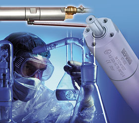
The second step examines the motor’s construction material. If operating in a dry surrounding atmosphere and in normal stationary production, an inexpensive air motor made from cast iron will be sufficient. “Deprag offers a wide spectrum of low priced Basic Line motors. For installation in robots and machines there are a variety of grinding motors, drilling motors and milling motors available which are distinguished by their low weight and compact size,” explains Dübbelde. For use in the food industry, pneumatic motors must be able to withstand cleaning agents and steam. The Deprag Advanced Line motors with external parts made from stainless steel are additionally sealed and lubricated with food industry standard USDA-H1 grease. Pneumatic drives can even be operated underwater. In this case it is essential to determine the water depth required. If the motors must be started underwater they can be used up to a depth of 5 metres. If the motors are started on the surface and then submerged, they can be used to a depth of up to 20 metres without damaging the motor. If the motor must be sterilisable as required in some medical technology applications, then the motor can be equipped with special vanes. It is important to speak to the air motor manufacturers in advance about an application and to describe it in as much detail as possible.
Motor power
The next step is the calculation of the theoretic motor power. Motors which are designed for use in only one rotational direction are more efficient than reversible motors. When determining the rotational direction, the pneumatic expert looks towards the motor shaft from the air inlet. This is the other way around for electric motors where the rotational direction is specified by looking at the motor spindle. First the required working point of the motor is determined – the desired nominal torque and speed under load. The most economic use of the motor (least wear and least air consumption) is attained by running close to the nominal speed. The characteristic curve of an air motor shows that it reaches its maximum torque just before standstill (around twice the specified nominal torque). At the nominal speed the air motor reaches maximum power. With the formula: nominal torque times working speed (nominal speed) divided by 9550 the theoretically required power in kW can be found.
In manufacturers’ catalogues, performance data is based on varied operating pressures. At Deprag this is 6 bar. If the application only has 5 bar directly at the motor then the motor loses 23% of power. If there is only 4 bar available then motor power is reduced by 45%. A differing operating pressure is so decisive that it must be taken into consideration at the start of the design phase using the adjustment table in order to avoid nasty surprises. Next the air supply volume must be ensured which is specified by the air consumption in the manufacturers’ details. Every reduction in the width of the opening has an effect on the air volume, whether on the feed hose itself or due to connection parts, filters, oilers or exhaust hose and silencer. “I recommend an exhaust air throttle to my customers to regulate their speed”, explains Dübbelde. “Using a throttle on the supply air reduces the speed of the motor but at the same time the torque is reduced. Exhaust air throttles can reduce the speed without great loss of torque. The exhaust throttle means that my customers can better utilise the wider working range which air motors provide.” The optimal life span and performance of an air motor is reached with lubricated running (one to two drops of oil per cubic metre of air consumption). Unlubricated operation can lead to a loss of power of around 10 to 20%.
Integration of the motor
If the right motor with the required power has been found, whether stainless steel or cast iron, then the next step is to integrate it into the design. Deprag provides various spindle designs and individual fixing methods. A complete solution is often better value than seeking a gear solution separately. Within the Deprag motor range there are numerous air motors with integrated planetary gears, spur gears and worm gears. If additional safety in the design is required then a holding brake can be recommended. For use in potentially explosive environments there are also options with the required ATEX certification. Integration is concluded with the technical verification of the maximum permissible axial and radial load on the drive spindle of the air motor.
Durability
Air motors are powerful, durable and robust. Adherence to the framework conditions determined during the design phase and compliance with the instruction manual will ensure the longest possible life of the drive. These conditions include adhering to the recommended air quality, lubrication, maintenance intervals, maximum feed hose length (3 metres) and opening widths of the feed hose and connection parts.
Purchase price and running costs
Finally, the purchase price is the predominant consideration in the acquisition of a new drive system. But the designer should also take into account running expenses and consider the operating costs for maintenance and servicing. When planning and selecting a new system the question must be asked: how readily available are replacement parts and what are their prices? Maintenance and repair service quotations ensure that this is calculable. The Basic Line air motors from Deprag are particularly maintenance friendly. The patented vane exchange system enables the vanes to be replaced quickly using a key and tweezers directly on the machine. The operating costs are determined by the air consumption. The right choice of motor sets the course for low running costs. The closer the motor runs to nominal speed (50% of the idle speed), the more efficiently the air is used.
Deprag Schulz has been using compressed air as a working medium for many decades and the company’s air motors and air tools are well established on the international market. Innovation and continuous improvements have made this medium-sized machine building firm into a leading manufacturer. Dübbelde concludes, “Around 85% of our projects in the field of air motors are special solutions which have been quickly and simply realised from our standard programme.” Deprag’s other core competencies include screwdriving technology, automation and air tools. The owner-managed family business employs 600 employees and has representatives in over 50 countries.
Dowson & Dobson, part of the Actum Group, is the exclusive agent for Deprag in South Africa.

© Technews Publishing (Pty) Ltd | All Rights Reserved

 printer friendly version