


An improved strategy for assessing and testing of motor-VSD combinations is proposed.
It has been proposed that the following be included into a South African National Standard, initially as an amendment/annex, and SANS 10086 has been earmarked as an appropriate place for the document. However, before such action is pursued, the South African Flameproof Association (SAFA) wishes to solicit comment on the proposal. (Hence the publishing of this article).
Concerns have been raised in the literature regarding the use of variable speed drives feeding motors (low voltage and medium voltage) in hazardous areas. When an explosion protected (Ex) motor is driven by an adjustable speed power drive system, more popularly known as a variable speed drive (VSD), more heat is created under certain operational conditions. In a hazardous location, this affects the temperature class of the motor (indicative of its capability to ignite the explosive atmosphere) adversely and may result in an unsuspecting end user experiencing an explosion.
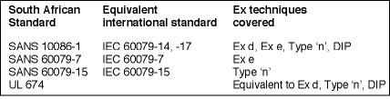
Adjustable speed power drive systems are covered extensively in SANS IEC 61800-2 (low voltage) and IEC 61800-4 (medium voltage). An application guide for motors fed from variable speed drives is provided in SANS 60034-17. These documents do however not provide specific requirements for variable speed drive motor combinations for use in hazardous areas. Recently, useful guidelines have, however, been developed to address power drive systems in hazardous areas.
Assessment/testing and certification of the motor-VSD combination is the South African legally recognised method to establish the ignition properties of the combination. An appropriate assessment and test methods for motor-VSD applications are yet to be formulated.
Factors causing additional ignition sources in VSD applications
The additional heat and electric stresses created in motors by VSD supplies are of course not only a concern in hazardous location applications but also in general applications due to reduced times to failure. Both motor standards and VSD standards are therefore addressing performance and effective combination of motors and VSDs and to limit the detrimental effect on motor life. However, the focus until recently has been mainly on electrical/performance issues.
The concern that increased heat may generate temperatures in excess of the certified temperature class value of an explosion protected motor in a hazardous location is very relevant in view of the many retrofits being currently made in South Africa to explosion protected motors, some possibly without re-certification.
Electrical and electromagnetic losses
In a squirrel cage induction motor, the energy losses producing additional heat are caused by mainly (a) resistance heating of the stator windings and rotor (typically 70% of total losses) and (b) electromagnetic losses created in the stator and rotor laminations (typically 25% of total losses).
The harmonics created by a VSD results in further energy losses, particularly in the rotor. For example, the deep-rotor bar design of some motors causes significant energy loss and heating. This is especially applicable in association with most low voltage (LV) VSDs and some medium voltage (MV) VSDs.
Some modern MV variable speed drive technologies, eg, the multilevel voltage source inverter (ML VSI) and the current source pulse width modulated (CSI PWM), are however not associated with significant current harmonics and rotor bar designs associated with these motors do not have a significant impact regarding additional temperature rise.
Transient voltage peaks also put electrical stress on the winding insulations; many of the current standard motor designs will suffer from reduced lifetimes when used with VSD supplies. In addition, premature insulation failures create additional ignition sources. An above standard insulation specification and/or techniques to reduce the voltage transients are required to prevent sparks (ignition sources).
An additional ignition source (associated with sparks) is associated with bearing currents and suitable techniques to limit the bearing currents are described in the annexure of the original document. This article focuses on the risk associated with an excessive temperature.
Startup
Startup is traditionally the hottest part of the operational cycle of an induction motor. The motor start-up current is typically 6-10 times the rated value, whereof the duration depends on the load torque speed characteristic (especially important to consider constant load versus speed applications, eg, a slurry pumping application) and system (load and motor) inertia.
A VSD supply acts as a soft-start. The reduced energy loss will normally more than compensate for the harmonics effect. Startup through a VSD supply will therefore generally not affect the temperature class of a motor negatively and may even improve the temperature rating of for example, Type 'n' motors with S3 and higher duty cycles. (Note - Startup is not taken into account for S1 and S2 Type 'n' motors).
European certification authorities (Notified Bodies) often require pre-start purging for medium voltage Type 'n' motors that are started directly on line (sparking can occur in some cases). MV Type 'n' motors fed by variable speed drives normally do not require pre-start purging since the chance of sparking is minimal.
Low speed
For directly driven fan-cooled motors (eg, TEFC motors) there is a direct relation between motor/fan speed and temperature. For example, a speed reduction of 40% may reduce cooling by 50%. In addition, reduced speed is associated with reduced motor power and depending on the type of load (eg, a flat load-speed curve), increased overheating can occur at lower speeds.
High speed
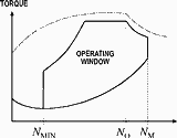
Motor-VSD performance curves illustrate that the maximum output torque drops off significantly above 55 Hz and is typically reduced by 25% at 65Hz in the field weakening region (constant power). Refer to Figure 1 for an example. Should the load remain constant or even increase at higher speeds, increased current will cause additional heat.
Speed ramping
During a change in speed, additional transient heating can (similar to startup) be caused by increased load with increasing speed due to inertia. This effect will be more pronounced with fast speed changes, or when frequent speed changes are made.
Medium voltage and multilevel low voltage variable speed drives - additional considerations
It has been stated that some modern medium voltage variable speed drive technologies, eg, the multilevel voltage source nverter (ML VSI) and the current source pulse width modulated (CSI PWM) are not associated with significant current harmonics. The additional heating due to current harmonics is therefore almost eliminated. Certification requirements should be adjusted accordingly. Note that the reduced cooling at lower speed is still applicable and forced ventilation will still be required in some cases (eg, for some constant torque loads). Note that the cable length limitations and the generation of dangerous voltage peaks are also negligible for some medium voltage topologies. The applicable explosion protection standard should therefore distinguish between low and medium voltage variable speed drives.
Consideration should also be given to specific requirements for multilevel low voltage variable speed drives and other alternative technologies where the output waveforms of VSDs are more sinusoidal.
The performance curves for a motor-VSD application in a hazardous location must be carefully analysed in selecting the correct motor and drive. A suitable technique is to de-rate the motor. Particular care should be taken to consider the full speed range.
Sensitivity of Ex motors to these ignition sources
The temperature rating or temperature class of an explosion protected motor can for the purpose of this article be defined as 'the maximum temperature achieved by an external or internal motor surface that may serve as a source of ignition of an external explosive gas/vapour/mist/dust atmosphere with which the motor is in contact'.
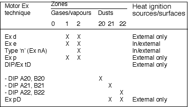
The most common explosion protection techniques applied to motors are flame proofing (Ex d), Increased Safety (Ex e), Type 'n' or non-sparking (Ex nA), Pressurisation (Ex p) and Dust Ignition Protection (DIP) as per Table 1.
The sensitivity of Ex motors to the additional ignition sources differs depending on the type of explosion protection applied, as follows:
Internal versus external surfaces
Ex motors can be placed in two groups as regards their temperature class and heat ignition sensitivity in VSD applications:
a) Motors using Ex techniques involving enclosure protection and therefore less sensitive to heat losses in the rotor and stator. The enclosure is the only heat ignition source. These are Ex d, Ex p and DIP motors.
b) Motors using Ex techniques involving prevention of ignition caused by the internal components of the motor and therefore more sensitive to heat losses in the rotor and stator. These are Ex e and Type 'n' motors, in the latter case particularly non-sparking or Ex nA motors (which form the majority).
Frequency of exposure to explosive atmosphere
Type 'n' and DIP A22 or DIP B22 motors are used in respectively Zone 2 and Zone 22 hazardous locations where an explosive atmosphere only occurs under abnormal conditions (typically less than 10 hours total per year). As a result, ignition sources created by infrequent operational conditions, such as start-up temperatures on S1 and S2 motors, may be excluded (except 'sparking' during start-up associated with MV motors).
Premature failure
Ignition sources created by premature failure will be mainly inside the motor enclosure; therefore the same arguments as mentioned under 'Internal versus external surfaces' apply.
Current certification requirements
The temperature rise effects caused by VSD-operated motors are considered in the following standards on explosion protection:
In summary, Ex d and DIP motors need not be physically tested in combination with their VSD provided that thermistor protection is applied. (The requirement for thermistor protection must however be included in the certification and marking as a special condition of use or 'X'.) In all other cases, testing of the motor-VSD combination is required, except that an assessment will be sufficient if a VSD used with a Type 'n' motor has a proven low harmonic output and the load torque speed curve is below the motor-VSD capability curve. This may be especially applicable to MV power drive systems where pre-site testing may not be practical/economical.
The standards do not specify what quality control measures need to be applied subsequent to type testing. Type testing means that the design characteristics of a particular combination of Ex motor and VSD (as specified by, for example, the VSD model and the motor specification) are determined and a type test report and certificate (IA certificate) is issued by an approved test laboratory (ATL).
The normal requirement is that further applications must be covered under an approved product certification scheme or batch testing by an ATL must be carried out.
Shortcomings of the current requirements
The basic problem with the above standards is that the effects of increased electrical stress (especially on retrofits), reduced cooling, increased current and high switching rates, as discussed in section 2 are not adequately addressed. Specific issues are:
a) For Ex d and DIP motors, thermistor protection of the stator windings is considered inadequate protection. It is possible that in applications where a rotor design developing high temperatures or a VSD with an unfavourable harmonics component is present (or both), external shaft and end shield surfaces may exceed the maximum safe temperature. The installation of additional thermistors on the end shields should be considered as a possible solution and an additional requirement.
b) For Type 'n' motors, the option to certify a motor-VSD combination merely on the basis of Umax and dU/dtmax output characteristics of the VSD may for the applications mentioned in (a), result in unsafe high temperatures.
c) Guidance should be given as regards parameters critical to safety that should be evaluated and specified as part of the certification conditions, for example dynamic speed variations, type and length of the motor-VSD interconnecting cable, and VSD protective devices.
d) Guidance should be given on test methodologies. For example, it may not be economical or practical to load test an MV motor in combination with the VSD.
e) Consideration should be given (possibly via a risk assessment route) to the screening of drives for suitability to be used with certain old-technology motors, as premature failure of these motors may cause unacceptable ignition risks.
Note that the above remarks should by no means be construed as criticism of the existing standards. Standards have to naturally evolve in line with technology.
A more comprehensive approach
The association believes that three options for assessment and testing should be used:
a) In-situ testing (ie, as-installed) of the motor-VSD combination under conditions selected to be worst-case for the intended application, to determine the motor temperature profile. A hotter temperature class may be allocated to the motor-VSD combination, provided that this temperature class is compatible with the area classification.
b) Dynamometer load testing similar to (a) ie, only the intended application will be covered.
c) The most comprehensive approach is dynamometer load testing to determine a safe torque-speed envelope for a specific target maximum temperature. This curve will indicate the de-rated capability of the motor in order to facilitate the temperature requirements of the hazardous location. The original temperature class of the directly-driven motor can be used as the criterion, or a more severe temperature class that stills provides sufficient protection in the hazardous area where the application will be used can be acceptable.
The curve shall be valid for all operating conditions as specified.
Data required
In all of the above approaches the parameters affecting the motor temperature have to be defined to ensure appropriate control in the field installation. These parameters include:
* The motor specification, eg, electrical rating and explosion protection rating. Indication should be given that a more severe temperature class could be accepted.
* The VSD specification, including input and output protection and control method, eg, vector control or scalar control (V/f control).
* The type and length of cable connecting the motor and the VSD.
* The motor cooling arrangement (internal as well as external, eg, forced ventilation).
* Temperature protection on the motor.
Note
Temperature protection is optional, provided that the installation and operating conditions are controlled; this will normally require the equipment and installation to be supplied under a product certification scheme or to be individually assessed/batch tested.
* The load versus speed values or curve.
Notes
1. If a safe torque-speed envelope has been determined as discussed in section 4.3, the load values/curve can be superimposed on this curve (see Figure 1); if the load requirement falls within the envelope, no further testing will be required.
2. By arrangement between the user and supplier, an agreed safety margin can be superimposed on the safe torque-speed envelope.
* The motor duty cycle, dynamic variations (including minimum and maximum acceleration rates) and start-up conditions (no-load curve, full load curve or partially loaded curve; and the required ramp-up time).
* The output of the VSD, including protective settings and equipment (peak voltage, peak voltage rise or fall rate associated with a specific installation shall be specified). The thermal protection model associated with the derating curve shall be documented. In this case the control of heating is achieved by limiting the current to the motor associated with a specific frequency.
The security arrangement for preventing unauthorised re-programming of the VSD must also be reported.
Quality management
Appropriate quality management would require that the correct installation of type-tested combinations be verified by an approved test laboratory, unless the supplier operates under an accepted product certification scheme.
Conclusions and recommendations
The above considerations could serve as a basis for discussion. The hazards associated with the use of VSDs on motors in hazardous locations are particularly relevant at the current time in South Africa because many retrofits of VSDs to previously direct-powered applications are carried out and not all drive and motor suppliers primed on the application of their products in hazardous locations.
Standards should be updated to reflect the requirements for motors in hazardous areas fed by variable speed drives. It is proposed that a working group be formed (consisting of manufacturers, certification authorities, consultants and industry) to address the concerns for specification, certification and testing of power drive systems with motors (both medium and low voltage) in hazardous areas.
The results of the working group should be reflected in SANS 10086 and SANS 10108. The working group should consult with international committees and/or working groups working in the same field. Furthermore a StandSA guideline document on the topic should be produced. The interface between the motor standards, variable speed drive standards and hazardous electrical equipment standards should be better defined.
Readers note that the original document, with full bibliographic references, can be obtained from SA Flameproof Association.
Send comments/queries to Paul Meanwell, chairman, SA Flameproof Association, [email protected]


© Technews Publishing (Pty) Ltd | All Rights Reserved

 printer friendly version