


Many years ago there was a popular quiz programme on TV, hosted by Anne Robinson, where the players voted in each round to determine who was the weakest link. Which is the weakest link in a control loop? The answer, without any doubt is that, in most cases, the final control element is the weakest link.
As mentioned in the previous article, the elements of the control loop consist of the process itself, the transmitter, the controller, and then the final control element. There are many types of final control elements, ranging from simple resistive heating elements through to more sophisticated devices such as variable speed pumps; but, in most plants the final element consists of a valve, an actuator, a positioner and an I/P current to pneumatic converter. Pneumatically-actuated valves have been in use for well over a century. They are simple and reliable, but are not very sophisticated or accurate devices. This is one of the main reasons why a positioner should always be used with this type of actuator.
In general, about 80% of all problems are due to faults in the final control element. The problem lies in the fact that valves are mainly mechanical devices, and must face all sorts of possible challenges, such as high and possibly varying pressure, friction, abrasion, corrosion, loose linkages and hysteresis, to name a few.
What is the actual purpose of the final control element? Simply put, its function is to translate a 0-100% signal from the controller’s output into an actual physical happening. The controller compares the actual value of the process variable (PV) with the SP setpoint (SP), and performs a relatively uncomplicated mathematical calculation that outputs a signal (called, by us, the process demand − PD) that demands that the final control element should go to a position where the actual desired quantity of process fluid or substance is fed into the process in order for the PV to reach the SP.
As an example, say a heat exchanger is heating a process fluid by injecting steam into the other side of the exchanger, and if the PD is at 55%, then the final control element is required to feed exactly 55% of the total range of the steam flow into the exchanger. The quicker and more accurately the final control element complies with that demand, the better the control, with the least variance.
When a control valve is really bad, the control can get to the point where it just cannot work, and sometimes it becomes absolutely necessary to get the valve fixed, or if this is not possible, to have it replaced. In spite of this, I have often found people still believing that a ‘miracle’ tune will sort out the problem. I have come across cases where they spend literally days and even weeks trying different tuning to get it to work, all to no avail.
The example given in this article is of a combustion air flow in a furnace in a petrochemical refinery. It was vital that the furnace temperature should be kept constant at SP, as quite a few downstream processes were dependent on it. However the temperature was usually not at its SP. Investigation revealed that the problem was related to the performance of the combustion air flow, which did not respond quickly enough to deal with load disturbances on the temperature process. This was a rather unusual problem, as airflow is such a fast process compared with temperature, and even rather poor flow control will not usually affect the temperature too much.
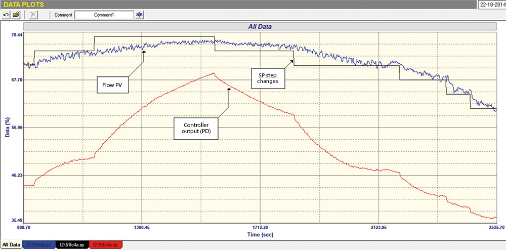
Figure 1 shows a recording of an As Found closed loop test on the flow loop, where step changes were made on the SP with the original tuning parameters in the controller to judge the control response. It was found that the tuning was abysmally slow, typically taking over 25 minutes for the process to respond to a 3% change in SP. On discussing this with the C&I; staff, I was told that they couldn’t get it to work faster as it tended to go into what they described as ‘crazy cycling’ as soon as they tried to speed it up. Normally, a flow loop should fully respond to a small SP step like that in a few seconds.
A second interesting thing seen in the test was that on the second upwards step of SP, the PD had to move much more than it did on the first step, even though the two steps were of equal size. This could have indicated several problems, including non-linear installed valve characteristics. However, on the first reverse step downwards, the PD had to move much less. This was a little puzzling, and may also have indicated that the valve was very sticky on opening.
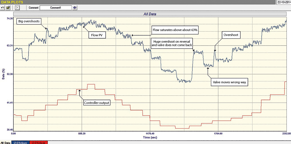
An open loop test was then performed on the flow loop, making step changes on the PD, and this shown in Figure 2. This is quite interesting as it shows that there were several serious problems with the valve. These were:
1. When the valve reversed from the closing direction, there were sometimes huge overshoots when it moved in the opening direction again. On some occasions, the valve then recovered and moved slowly back down to the correct position. However, it sometimes did not do this and stuck in the overshoot position.
2. There were some occasions where the valve also had big overshoots on other opening steps.
3. These occurrences made the valve effectively non-repeatable, and really inhibited good control.
4. There did appear to be some non-linearity in the valve installed characteristics. However, of more importance, and very seriously, the flow started saturating above 63%. A subsequent test (not shown here) showed that the maximum flow that could be obtained with the valve fully open was 76%. Under normal operating load conditions the flow SP was just over 70%. Good control in this saturated region was almost impossible. As mentioned above, the closed loop test in Figure 1 shows clearly how much the PD had to move on the second upwards SP step to try and get the PV to SP. The reason for this saturation was most likely insufficient upstream pressure in the air stream.
These findings show that good automatic control of the flow will not be possible if the saturation problem is not sorted out, and if the valve is not fixed or replaced to follow the PD properly. Once again it can be seen how very important it is to first analyse a loop thoroughly to determine if there are any problems before even thinking of tuning the controller.

Michael Brown is a specialist in control loop optimisation, with many years of experience in process control instrumentation. His main activities are consulting and teaching practical control loop analysis and optimisation. He now presents courses and performs optimisation over the internet. His work has taken him to plants all over South Africa and also to other countries. He can be contacted at: Michael Brown Control Engineering CC,


© Technews Publishing (Pty) Ltd | All Rights Reserved

 printer friendly version