


Among the basic elements of virtually every hydraulic system is a series of fittings for connecting tube, pipe, and hose to pumps, valves, actuators, and other components.
If the components within hydraulic systems never had to be removed, connections could be brazed or welded to maximise reliability. However, it is inevitable that connections must be broken to allow servicing or replacing components, so removable fittings are a necessity for all but the most specialised hydraulic systems. To this end, fitting designs have advanced considerably over the years to improve performance and installation convenience, but the overall function of these components remains relatively unchanged.
Fittings seal fluid within the hydraulic system by one of two techniques: all-metal fittings rely on metal-to-metal contact, while O-ring type fittings contain pressurised fluid by compressing an elastomeric seal. In either case, tightening threads between mating halves of the fitting (or fitting and component port) forces two mating surfaces together to form a high-pressure seal.
All-metal fittings
Threads on pipe fittings are tapered and rely on the stress generated by forcing the tapered threads of the male half of the fitting into the female half or component port, Figure 1. Pipe threads are prone to leakage because they are torque-sensitive - over-tightening distorts the threads. Moreover, pipe threads are prone to loosening when exposed to vibration and wide temperature variations - certainly no strangers to hydraulic systems.
Seepage around threads should be expected when pipe fittings are used in high-pressure hydraulic systems. Because pipe threads are tapered, repeated assembly and disassembly only aggravates the leakage problem by distorting threads, especially if a forged fitting is used in a cast-iron port. Thread sealant compound, a potential contaminant, is recommended for pipe fittings, which is still another reason why most designers consider them to be obsolete for use in hydraulic systems.
Flare-type fittings, Figure 2, were developed as an improvement over pipe fittings many years ago and probably remain the design used most often in hydraulic systems. Tightening the assembly's nut draws the fitting into the flared end of the tubing, resulting in a positive seal between the flared tube face and the fitting body. The 37° flare fittings are designed for use with thin-wall to medium-thickness tubing in systems with operating pressures to 20 MPa. Because thick-wall tubing is difficult to form to produce the flare, it is not recommended for use with flare fittings. The 37° flare fitting is suitable for hydraulic systems operating at temperatures from -54 to 200°C. It is more compact than most other fittings and can easily be adapted to metric tubing. It is readily available and one of the most economical.
The flareless fitting, Figure 3, gradually is gaining wider acceptance in the US because it requires minimal tube preparation. It handles average fluid working pressures to 20 MPa and is more tolerant of vibration than other types of all-metal fittings. Tightening the fitting's nut onto the body draws a ferrule into the body. This compresses the ferrule around the tube, causing the ferrule to contact, then penetrate the outer circumference of the tube, creating a positive seal. Because of this, flareless fittings must be used with medium or thick-walled tubing.
O-ring-type fittings
Surprising as it may seem, leakage in hydraulic systems could have been eliminated more than a generation ago.
Although leak-free hydraulic operation had always been desirable, the need became more acute with higher operating pressures that became necessary during World War II, primarily in the hydraulic systems of military aircraft. Until then, common operating pressures had hovered around 5,5 to 10 MPa. The post-war era ushered in systems designed to operate at pressures to 6,9 MPa and higher on applications where rapid cycling and high shock pressures were present. It was not long until pressures climbed to 17 MPa and 20 MPa - which certainly are not uncommon today.
Faced with increased hydraulic fluid leakage brought on by higher pressures, a consortium of fittings manufacturers - working under the umbrella of SAE's Committee on Tubing, Piping, Hoses, Lubrication, and Fittings - undertook solving the problem. Their joint effort in the early 1950s culminated in the straight-thread design, which ultimately became known as the SAE straight-thread O-ring boss.
Fittings that use O-rings for leak-tight connections continue to gain acceptance by equipment designers around the world. Three basic types are now available: SAE straight-thread O-ring boss fittings, face seal or flat-face O-ring (FFOR) fittings, and O-ring flange fittings. The choice between O-ring boss and FFOR fittings usually depends on such factors as fitting location, wrench clearance, or individual preference. Flange connections generally are used with tubing that has an OD greater than 22 mm or for applications involving extremely high pressures.
O-ring boss fittings seat an O-ring between threads and wrench flats around the OD of the male half of the connector, Figure 4. A leak-tight seal is formed against a machined seat on the female port. O-ring boss fittings fall into two general groups: adjustable and non-adjustable. Non-adjustable (or non-orientable) fittings include plugs and connectors. These are simply screwed into a port, and no alignment is needed. Adjustable fittings, such as elbows and tees, need to be oriented in a specific direction.
The basic design difference between the two types is that plugs and connectors have no locknuts and require no back-up washer to effectively seal a joint. They depend on their flanged annular area to push the O-ring into the port's tapered seal cavity and squeeze the O-ring to seal the connection. Adjustable fittings are screwed into the mating member, oriented in the required direction, and locked in place when a locknut is tightened. Tightening the locknut also forces a captive backup washer onto the O-ring, which forms the leak-tight seal. Assembly is always predictable, because technicians need only make sure that the backup washer is firmly seated on the port's spot face surface when the assembly is completed and that it is tightened properly.
The FFOR fitting forms a seal between a flat, finished surface on the female half and an O-ring held in a recessed circular groove in the male half, Figure 5. Turning a captive threaded nut on the female half draws the two halves together and compresses the O-ring.
Fittings with O-ring seals offer a number of advantages over metal-to-metal fittings. While under-or over-tightening any fitting can allow leakage, all-metal fittings are more susceptible to leakage because they must be tightened to within a higher, yet narrower torque range. This makes it easier to strip threads or crack or distort fitting components, which prevents proper sealing. The rubber-to-metal seal in O-ring fittings does not distort any metal parts and provides a tangible 'feel' when the connection is tight. All-metal fittings tighten more gradually, so technicians may have trouble detecting when a connection is tight enough but not too tight.
On the other hand, O-ring fittings are more expensive than their all-metal counterparts, and care must be exercised during installation to ensure that the O-ring does not fall out or get damaged when the assemblies are connected. In addition, O-rings are not interchangeable among all couplings. Selecting the wrong O-ring or re-using one that has been deformed or damaged can invite leakage. Once an O-ring has been used in a fitting, it is not re-usable, even though it may appear free of distortions.
Some manufacturers offer specially designed, high-pressure fittings that are equal in leak and weep resistance to FFOR fittings and interchangeable with a number of international fittings. Testing has shown these new designs to surpass all requirements with no evidence of leakage when exposed to vibrations up to 15 times more severe than those experienced on a typical hydrostatic drive. These designs may appear similar to standard fittings, but should not be mated with fittings from different manufacturers.
Fittings for tubing larger than 25 mm OD have to be tightened with large hexnuts which, in turn, require larger wrenches to enable workers to apply sufficient torque to tighten the fittings properly. To install such large fittings, system designers must provide the necessary space to give workers enough room to swing large wrenches. In addition, worker strength and fatigue could be factors affecting proper assembly. Extensions might be needed for some workers to exert an applicable amount of torque.
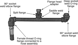
Fittings manufacturers have designed split-flange fittings so that they overcome both of these problems. Split-flange fittings, Figure 6, use an O-ring to seal a joint and contain pressurised fluid. An elastomeric O-ring rests in a groove on a flange and mates with a flat surface on a port - an arrangement similar to the FFOR fitting. The O-ring flange is attached to the port using four mounting bolts that tighten down onto flange clamps, thus eliminating the need for a large wrench when connecting large-diameter components. When installing flange connections, it is important to apply even torque on the four flange bolts to avoid creating a gap through which the O-ring can extrude under high pressure.

The basic split-flange fitting consists of four elements: a flanged head connected permanently (generally welded or brazed) to the tube, an O-ring that fits into a groove machined into the end face of the flange, and two mating clamp halves with appropriate bolts to connect the split-flange assembly to a mating surface.
All mating surfaces must be clean and smooth. Joints are more likely to leak if either of the mating surfaces are scratched, scored, or gouged. Additionally, wear tends to accelerate on O-rings which are assembled against rough surfaces. Where perpendicular relationships are critical, all parts must meet appropriate tolerances. While 1,6 mm. surface finishes are acceptable, most flange manufacturers prefer and recommend 0,8 mm finishes on mating surfaces to ensure leak-free connections.
In a properly designed split-flange assembly, the flange shoulder protrudes approximately 0,25 to 0,762 mm beyond the clamp face to ensure adequate contact and seal squeeze with the mating face, Figure 6. However, the clamp halves do not actually contact the mating surface. The most critical operation during assembly of a split-flange fitting to its mating surface is to make certain that the four fastening bolts are tightened gradually and evenly in a cross pattern. Air wrenches should not be used because they are difficult to control and can easily over-tighten a bolt.
Fully tightening one of the bolts while the others are still loose will tend to cause the flange to tip upward, Figure 8. This action pinches the O-ring, and the joint can then be expected to leak. When the bolts are fully tightened, the flanges sometimes bend downward until they bottom on the port face, and the bolts bend outward, Figure 8. Should flanges and bolts bend, they tend to lift the flange off the shoulder; once again, the result will be a leaking joint.
For more information contact Paul Heney, senior editor, Hydraulics & Pneumatics, 091 216 931 9476, [email protected], www.penton.com
Material for this article was extracted, with permission, from the 2004-2005 Fluid Power Handbook & Directory, copyright 2004, Penton Media, USA.


© Technews Publishing (Pty) Ltd | All Rights Reserved

 printer friendly version