


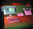
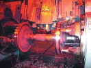
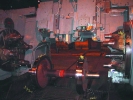
The Hegenscheidt portal wheel lathe is used in railway workshops around the country to cut the profiles on the train wheel surface. Some of these where installed as far back as the '60s, and their performance is no longer up to scratch with what is possible using modern electronics and software technology.
The original portal lathes were equipped with an hydraulic profile copying system consisting of a metal template and a follower that opens and closes valves that control the vertical and horizontal speed of the tool slides. The mechanical nature of this system makes wear inevitable - and changing from one profile shape to another requires changing templates. Adjustments on the template mechanism require skill and a considerable amount of time.
The new machine
The highly modified CNC/PLC portal is the result of a completely new approach that dispenses with the template copy system and the extensive relay logic. CNC/PLC technology made it possible to optimise the process of wheel turning. From an operator point of view it is more user friendly as many of the options are automatically selected. Using two CNC modules in one PLC rack on a common bus enable the machine to cut the selected profile according to a set of coordinates. Feed-rate and spindle speed are easily programmable and adjustments are made by simple tool correction.
Servo valves are used on each of the five positioning axes. Together with high-resolution ELGO magnetic position sensors on each cutting axis, it is possible to combine speed with accuracy to produce an optimised machining cycle. The servo valves have non-linear volume to speed operating curves, which allows very accurate flow-rate control. Special modules control the position-feedback equipped hydraulic valves. This allows interfacing the non-linear response of the valves to the required linear response needed for CNC command voltage operation. The diameter slide servo valve is equipped with on-board electronics thus allowing direct connection to the CNC control.
From an electrical point of view matters are much simplified as original hardwired relay logic is speedily and safely executed by software in the BOSCH CL350 PLC processing unit connected to a number of fieldbus I/O units based on Profibus DP. As a result there is a massive reduction in panel and interface cabling. Extensive automated diagnostics in the PLC and CNC makes it easier to locate and rectify problems, most without referring to documentation. For example, every fuse and circuit breaker in the electrical panel is monitored individually. The status of the CNC/PLC interface signals is visible through the CNC diagnostic modes to the operator/maintenance personnel. The status of the discreet I/O (24 V logic inputs) of the PLC is also visible on the CNC diagnostic screen, making hardware troubleshooting easy with the aid of the electrical schematics.
There are 64 possible error messages specific to the machine additional to extensive diagnostics built into each CNC control. The status of many pre-conditions for automatic wheel loading is visible to the operator in machine diagnostic mode MSD.
The Bosch CNC/PLC system
In order to position five axes, as well as to calculate the feed exactly according to spindle feedback, it is necessary to use two CNC control modules. The one CNC controls the left-hand tool slides and diameter (rough positioning) slide, and the other the right hand tool slides. Both CNC modules monitor the speed of the common spindle via a single encoder.
Communication between the two CNCs and PLC are done on a common interface consisting of 4-bytes extended inputs/outputs. The PLC addresses each CNC in turn, according to bus address, within one PLC program cycle. The operator screens for the CNCs are displayed on an industrial computer as two separate Windows applications. The computer connects to each CNC module via an RS232 interface. The operator may freely switch between the two screens, although only NC1 is used for the MMI (man-machine interface)
Customer programming language (CPL) similar to Pascal is used in the left hand CNC to provide the operator a convenient means of entering wheel data. The user-input screen prompts the operator for each data field and validates it when entered. The operator may accept or discard entries at the end of the entry process.
Wheel data consist of:
1. Profile type (21,22,14C3).
2. Original diameter.
3. Target diameter.
4. Wheel widths (separately for each side).
5. Side correction values (lateral correction for each wheel).
This information is written by the CPL program in the left hand CNC (NC1) first into a table and then transferred to the right hand CNC (NC2) via the PLC. In this way NC2 gets the data for the right hand wheel.
In order to maximise accuracy of the machine, it is required to accurately determine the most inner point of each wheel flange. On the original machine the so-called high spot (most inner point of flange) could not be detected. Integrated features of the CNC control detect the wheel flange positions to a suitable degree of accuracy within a very short time.
Using two roller devices (one for each side) fitted with proximity switches, the high-speed input on each CNC is switched and the exact switch point used to capture the flange position - similar in function to a measuring probe. The sensing rollers are mechanically protected against over-travel by software limits. Once the flange positions for a particular wheel are known, it will be remembered (stored in a table) until it is unloaded. The starting position of the profile is derived from the probe position together with lateral correction for inaccurately pressed wheels and width dimension.
In order to simplify profile position adjustments, use is made of a table in each CNC to allow for the following:
1. Lateral correction (relative to the sensed position of the wheel flange).
2. Calibration for diameter.
3. Search depth for sensing rollers.
4. Positioning of outside radius.
The profile is then cut incrementally from the start position, thus re-calculation of points are not necessary by the end-user when adjustments need to be made.
The profile part programs in the CNCs analyse diameter reduction and automatically calculates and executes an orderly stepped diameter reduction on up to three successive cuts. In order to minimise cycle time, the roughing cuts do not cover the full profile length, only to remove the excess material in the flange area. The feed is also courser on the roughing cuts. Status information informs the operator on the quantity and progress of cuts.
Optimising cycle time requires synchronisation of the two sides; thus the PLC has to ensure that the separate part programs running in the CNCs reaches the same processing point at certain times. The PLC also looks after peripheral devices and associated auxiliary functions including lubrication. Safety conditions are continuously monitored.
Loading the next wheel data
Whilst cutting, the operator enters the data for the next wheel, thus minimising waste time. The operator enters but does not accept data for the next wheel, thus allowing quick access to the current wheel data should a tool brake occur and the cycle restarted. Just before the current wheel is finished, the operator accepts data for the next wheel. No time is wasted.
The tool brake function interrogates each CNC directly thus maximising response time and reliability. The machine will automatically position itself at a safe height for loading for the next wheel at the end of the cycle.
The operator may load the wheel automatically or manually by means of a switch on the operator panel. Also, the operator may decide that the wheel should be automatically unloaded from the machine at the end of the cutting cycle. To save time the operator may terminate inside facing of the wheel at any point. (The original machine did not provide this function.)
Only one button needs to be pressed in order to cut a wheel set completely, minimising operator fatigue. The end user is able to easily make profile corrections by means of a simple table stored in each CNC. Complicated tool corrections are thus avoided. Corrections are possible for the lateral position, diameter and outside radius. This can be done while the machine is cutting. A CPL timer updating utility in NC1 diagnostic mode is used to modify timer values in the PLC. Part programs for the CNC are backed up in non-volatile memory residing in each CNC.
The hard drive of the PC is also used to back up the PLC program and other important information. The PC is additionally equipped with an Ethernet module thus allowing direct connection to another PC for say production planning purposes. Control Techniques' Mentor drives ensures that both main motors are contributing equally to the torque demand whilst regulating the turning speed to the value that is derived from the part program. The operator may override this default value according to cutting conditions.
Summary list of operations:
1. Machine is switched on and referenced for first wheel.
2. Operator starts wheel loading.
3. While wheel is being loaded, wheel data is entered for first wheel.
4. When wheel is loaded, cutting cycle is started.
5. While the wheel is being cut, data for the next wheel is entered.
6. After the cutting cycle is finished the wheel is unloaded automatically.
7. The next wheel is loaded and cutting starts automatically.
For more information contact Guenter Schmitz, Flexible Electronic Systems, +27 (0) 11 975 7000, [email protected], www.satool.com


© Technews Publishing (Pty) Ltd | All Rights Reserved

 printer friendly version